


 |
MMY820S - Mechanical Metallurgy - 2nd OPP - JUN 2023 |
|
|
1 Page 1 |
▲back to top |
nAm I BIA UnlVERSITY
OF SCIEnCE Ano TECHn OLOGY
FACULTYOF ENGINEERINGAND SPATIALSCIENCES
DEPARTMENTOF MECHANICALM, ININGANDPROCESSENGINEERING
QUALIFICATION: BACHELOR OF ENGINEERING IN METALLURGY
QUALIFICATION CODE: 08BMET
LEVEL: 8
COURSE CODE: MMY820S
COURSE NAME: MECHANICAL METALLURGY
SESSION: June 2023
DURATION: 3 HOURS
PAPER: THEORY
MARKS: 100
EXAMINER(S}
SECONDOPPORTUNITYQUESTION PAPER
Prof. Sofya Mitropolskaya
MODERATOR:
Prof Josias Van der Merwe
INSTRUCTIONS
1. Answer all questions.
2. Read all the questions carefully before answering.
3. Marks for each questions are indicated at the end of each question.
4. Please ensure that your writing is legible, neat and presentable.
PERMISSIBLEMATERIALS
1. Examination paper.
THIS QUESTION PAPER CONSISTS OF 5 PAGES (Including this front page)
|
|
2 Page 2 |
▲back to top |
Question 1 (25 marks]
(a) A low carbon mild steel at ASTM grain size of Nl (d=0,25 mm) has revealed rather poor yield
strength. Is it possible to triple the yield strength of the steel due to grain refinement to ASTM
grain size of NB (d=0,022 mm)? With the aid of the Hall-Petch equation:
ay = a" +k\\~
where oo and k are material constants, d is the grain size;
estimate the yield strength growth of this steel as a result of such grain refinement. Note that
for mild steel the lattice resistance stress Oo is small and can be neglected.
(15]
Initial grain size (mm)
Grain size after refinement (mm)
0,25
0,022
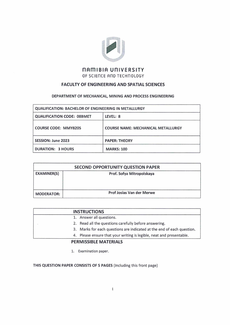
(b) With the aid of Griffith's analysis of the critical stress:
Omax = aa (1 + 2a/b),
estimate the stress concentration Omax in the vicinity of an elongated non-metallic inclusion
(Figure Ql). You may consider non-metallic inclusions as potential cracks. Assume the tensile
stress aa is applied in vertical direction and equals 50 MPa.
[10]
Figure Q1. Elongated non-metallic inclusions: length a=20 µm, width b=1 ~Lm
2
|
|
3 Page 3 |
▲back to top |
Question 2 (25 marks.
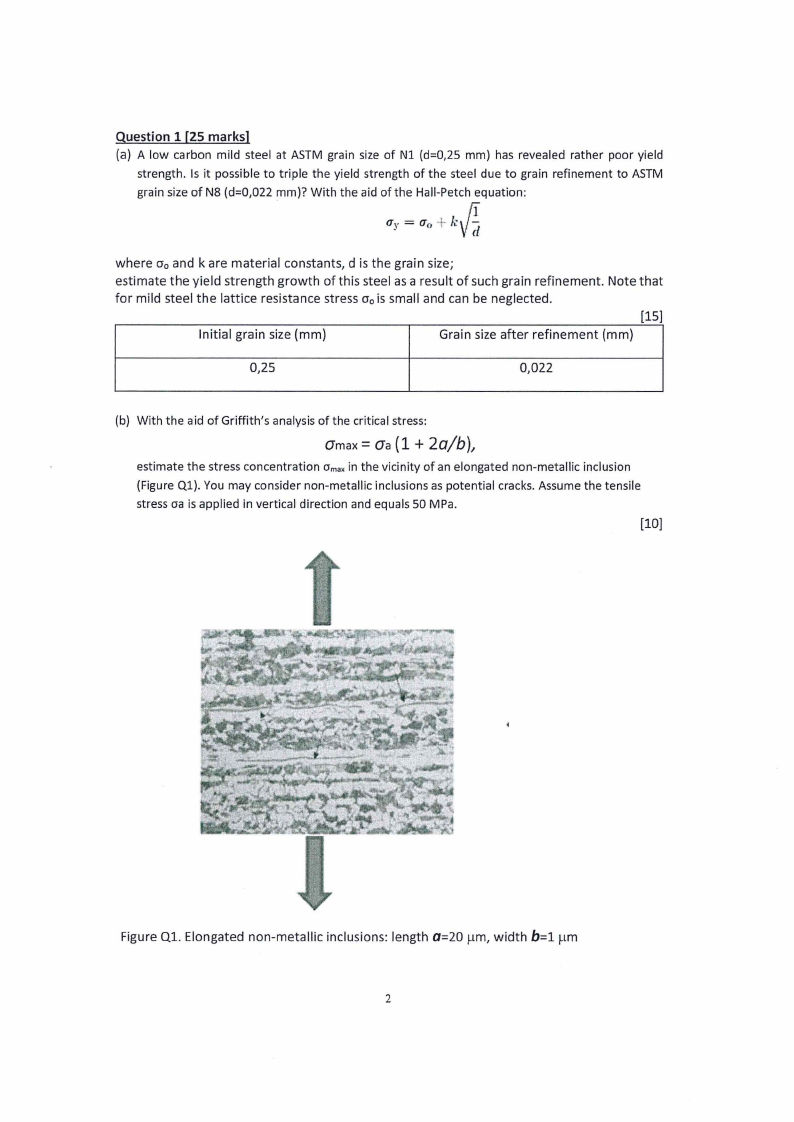
(a) You are asked to select a material for the teeth of a digger truck (Figure Q2-1). To do so
you need to prioritize the materials properties that matter. List the key material properties
required for the teeth of a digger truck.
[6]
Figure Q2-1. A digger truck.
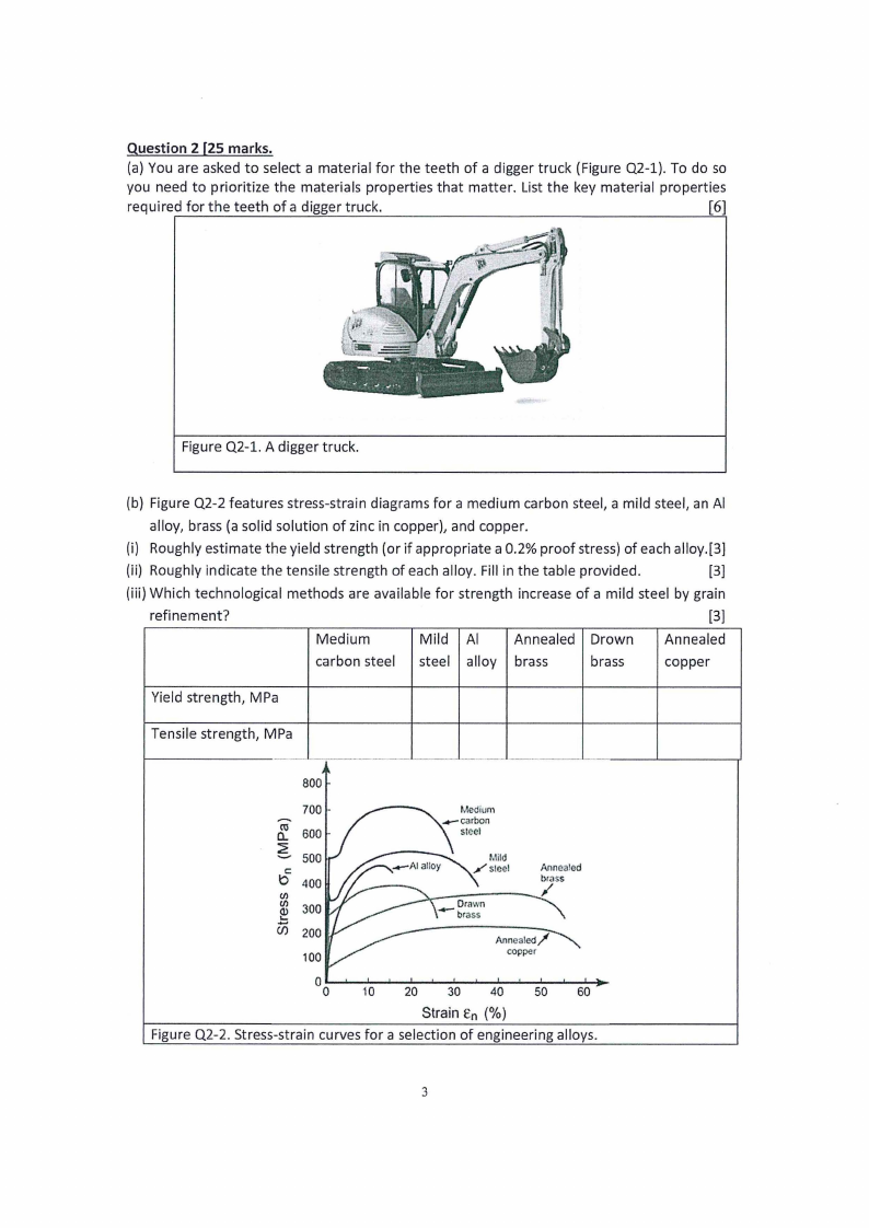
(b) Figure Q2-2 features stress-strain diagrams for a medium carbon steel, a mild steel, an Al
alloy, brass (a solid solution of zinc in copper), and copper.
(i) Roughly estimate the yield strength (or if appropriate a 0.2% proof stress) of each alloy.[3]
(ii) Roughly indicate the tensile strength of each alloy. Fill in the table provided.
[3]
(iii) Which technological methods are available for strength increase of a mild steel by grain
refinement?
[3]
Medium
Mild Al Annealed Drown Annealed
carbon steel steel alloy brass
brass
copper
Yield strength, MPa
Tensile strength, MPa
800
-a.c...o.....670000
500
C
b 400
C/)
C/)
.Q...).....
300
Cl) 200
100
Drawn
-brass
Annealed
brass
/
Annealed/
copper
0
0 10 20 30 40 50 60
Strain En (%)
Figure Q2-2. Stress-strain curves for a selection of engineering alloys.
3
|
|
4 Page 4 |
▲back to top |
(c) The critical strength 6c of zinc is as low as 2 MPa. Ultrasonic non-destructive inspection of a zinc
plate has revealed a crack 1 mm long (2a = 1 mm). Is it safe to operate such a plate under Griffith's
plain stress? Estimate with the aid of Griffith's criterion:
where o-cis the critical stress required for propagation of the brittle crack (Pa);
ys is the energy of the new surface area per unit of area;
E is Young's modulus (Pa)
a is a half-length of a critical crack that will propagate spontaneously; n = 3,14.
(10)
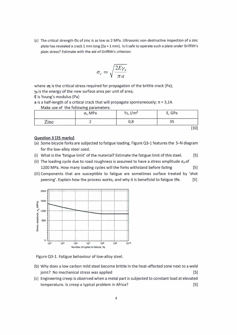
Question 3 [25 marks]
(a) Some bicycle forks are subjected to fatigue loading. Figure Q3-1 features the 5-N diagram
for the low-alloy steel used.
(i) What is the 'fatigue limit' of the material? Estimate the fatigue limit of this steel.
(5)
(ii) The loading cycle due to road roughness is assumed to have a stress amplitude Oa of
1200 MPa. How many loading cycles will the forks withstand before failing
(5)
(iii) Components that are susceptible to fatigue are sometimes surface treated by 'shot
peening'. Explain how the process works, and why it is beneficial to fatigue life.
(5)
2000 .P::====+=====:i====::::r:=====i=====+===:::::+1
I:-__ 1600 +·!---+----lf-----+----+---+-----H
f 1200 ·HI -------+r--_---'==l""'-,;;;;;;::t::::,::=j:::::t::::j:J
]t I -,- 800 ++---.,----<~-----r-----t---+-------+-1
(1)
<I)
<I)
iii
0 • .• •·•····
106
107
109
Number of cycles lo failure, N1
1010
Figure Q3-1. Fatigue behaviour of low-alloy steel.
(b) Why does a low carbon mild steel become brittle in the heat-affected zone next to a weld
joint? No mechanical stress was applied
(5)
(c) Engineering creep is observed when a metal part is subjected to constant load at elevated
temperature. Is creep a typical problem in Africa?
[5]
4
|
|
5 Page 5 |
▲back to top |
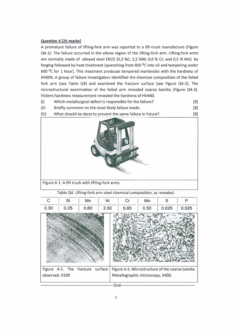
Question 4 [25 marks]
A premature failure of lifting-fork arm was reported to a lift-truck manufacture (Figure
Q4-l). The failure occurred in the elbow region of the lifting-fork arm. Lifting-fork arms
are normally made of alloyed steel EN25 (0,3 %C; 2,5 %Ni; 0,6 % Cr; and 0,5 % Mo) by
forging followed by heat treatment (quenching from 850 °cinto oil and tempering under
600 °cfor 1 hour). This treatment produces tempered martensite with the hardness of
HV600. A group of failure investigators identified the chemical composition of the failed
fork arm (see Table Q4) and examined the fracture surface (see Figure Q4-2). The
microstructural examination of the failed arm revealed coarse bainite (Figure Q4-3).
Vickers hardness measurement revealed the hardness of HV440.
(i) Which metallurgical defect is responsible for the failure?
[9]
(ii) Briefly comment on the most likely failure mode.
[8]
(iii) What should be done to prevent the same failure in future?
[8]
Figure 4-1. A lift truck with lifting-fork arms.
Table Q4. Lifting-fork arm steel chemical composition, as revealed.
C
Si
Mn
Ni
Cr
I Mo
s
pf
0.30
0.25
0.60
2.50
0.60
.,. .
I 0.50 0.025
0.025 f
Figure 4-2. The fracture
observed. Xl00
surface
.'
Figure 4-3. Microstructure of the coarse bainite.
Metallographic microscopy, X400.
---------------------------- ------------------------- -- End------------------------ --------------------------------
5