|
RMC711S - Rock Mechanics 314 - 1st Opp - June 2022 |
|
|
1 Page 1 |
▲back to top |
nAmI BIA un IVERSITY
OFSCIEnCEAno TECHnOLOGY
FACULTY OF ENGINEERING AND SPATIAL SCIENCE
DEPARTMENT OF MINING AND PROCESS ENGINEERING
QUALIFICATION: BACHELORS OF ENGINEERING IN MINING ENGINEERING
QUALIFICATION CODE: BEMIN LEVEL: 6
COURSE CODE: RMC711S
COURSE NAME: ROCK MECHANICS
SESSION: JUNE 2022
PAPER: THEORY
DURATION: 3 HOURS
MARKS: 100
FIRST OPPORTUNITY QUESTION PAPER
EXAMINER(S) Mallikarjun Rao Pillalamarry
MODERATOR: Prof. Mapani Benjamin
INSTRUCTIONS
1. Answer all questions.
2. Read all the questions carefully before answering.
3. Marks for each question are indicated at the end of each question.
4. Please ensure that your writing is legible, neat and presentable.
PERMISSIBLE MATERIALS
1. Examination paper.
2. Two Graph Papers
3. Mathematical Instruments
THIS QUESTION PAPER CONSISTS OF 4 PAGES (Including this front page)
|
|
2 Page 2 |
▲back to top |

|
|
3 Page 3 |
▲back to top |
Instructions: Answer Question 1 and any 4 other questions. Excess questions will not be marked.
Question 1 is compulsory.
Time allowed: 3 hours
Question 1 Short answer questions
(20)
a) What the difference between rock and rock mass?
b) What is the range of 'Q' value in 'Q' classification system?
c) What is the maximum length of drill core run used to measure RQD?
d) How do the water in the joints influence the stability of rock mass?
e) Which side the Mohr's circle moves when pore pressure is increased?
f) What are the parameters associated with Bieniawski's RMR?
g) Direction of major principal stress for a rock is 35° from x-axis. What is the major shear
stress direction with respect to y-axis [both x, y-axes are perpendicular to each other]
h) RQD is the first quantitative rock mass classification system developed by John Deer [ 1964].
Nevertheless, it has two major problems with respect to rock mass classification, what are
they?
i) In triaxial testing, which of confining stress and axial stress, is constant?
j) Shear strength failure criteria for a rock sample is 't = 25+ O"nTan 23.6°, then what is the
angle between failure plane and major principal stress direction? [2]
Question 2 Briefly discuss the following characteristics of discontinuities and their effect on stability (20)
of rockmass with diagrams wherever possible
a) Joint spacing
b) Joint orientation
c) Fracture aperture
d) Fracture roughness
e) Fracture filling
Question 3 A competent sandstone rock mass is fractured by three joint sets plus random fractures. The (20)
average RQD is 75%; the average joint spacing is 0.18 m. The joint surfaces are slightly
rough and slightly weathered. The joints are in contact with apertures generally less than 1
mm; no clay is found on the surfaces. The point load strength index of the sandstone is 3.5
MPa. The tunnel is to be excavated at 50 m below the ground level and the ground water
table is 20 m below the ground surface, thus large inflow of water expected. Estimate the Q-
value.
Question 4
a) What are methods used to measure in situ stresses and classify them according to the amount (6)
of disturbance caused during measurement
b) Briefly describe with help of figures, in situ stress measurement using flatjack method
(14)
|
|
4 Page 4 |
▲back to top |

|
|
5 Page 5 |
▲back to top |
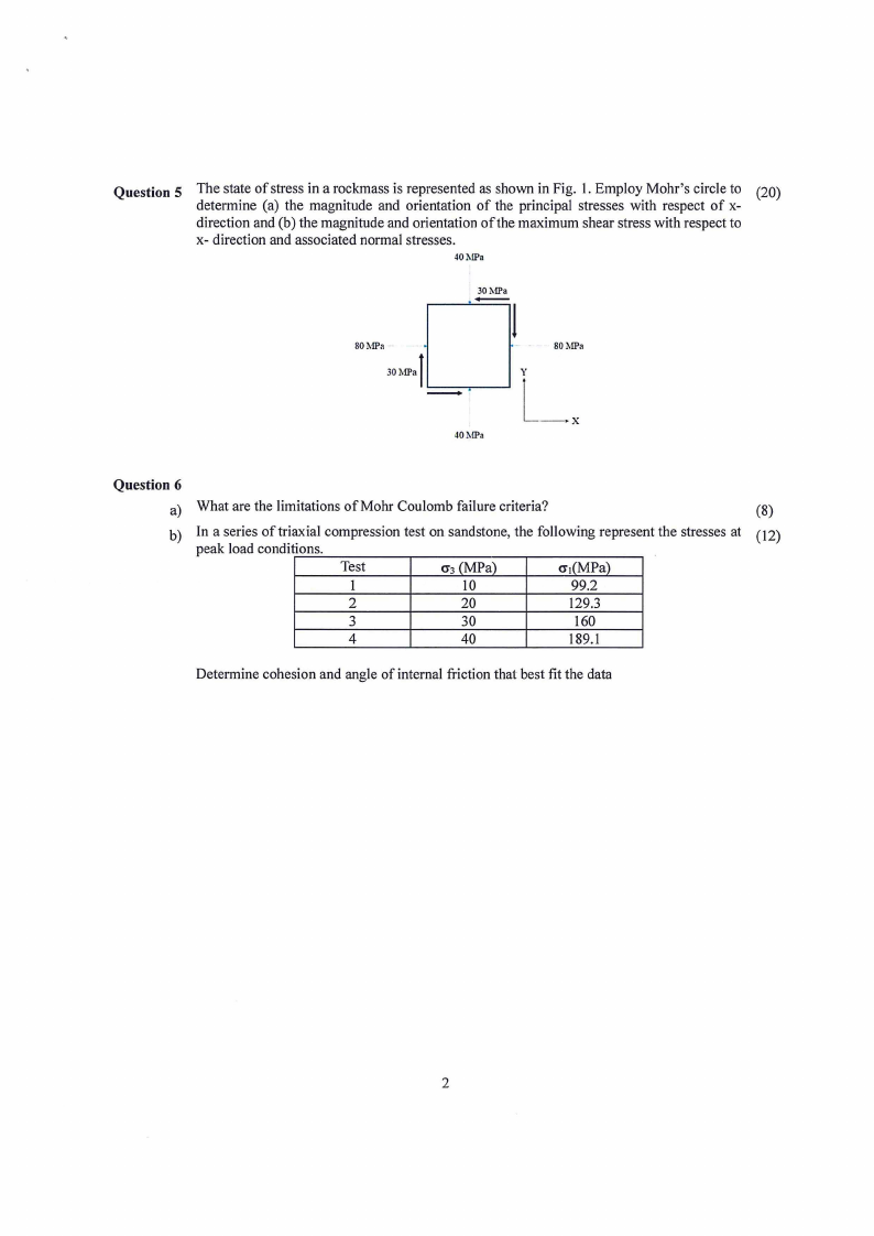
Question 5 The state of stress in a rockmass is represented as shown in Fig. I. Employ Mohr's circle to (20)
determine (a) the magnitude and orientation of the principal stresses with respect of x-
direction and (b) the magnitude and orientation of the maximum shear stress with respect to
x- direction and associated normal stresses.
40MPa
30MPa
80MPa -
l-30MPa
40MPa
-
80MPa
YL,
Question 6
a) What are the limitations of Mohr Coulomb failure criteria?
(8)
b) In a series of triaxial compression test on sandstone, the following represent the stresses at ( 12)
peak load conditions.
Test
cr3(MPa)
cri(MPa)
1
IO
99.2
2
20
129.3
3
30
160
4
40
189.l
Determine cohesion and angle of internal friction that best fit the data
2
|
|
6 Page 6 |
▲back to top |

|
|
7 Page 7 |
▲back to top |
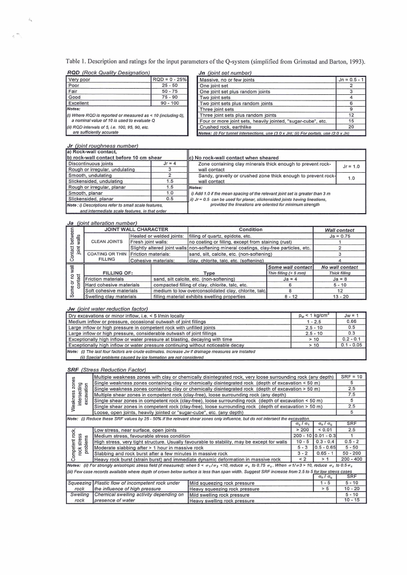
Table I. Description and ratings for the input parameters of the Q-system (simplified from Grimstad and Barton, 1993).
RQD /Rock Qualitv Oesiqnation)
Very poor
ROD= 0 -25%
Poor
Fair
Good
Excellent
Notos:
25 - 50
50 - 75
75 - 90
90 - 100
(i) Where ROD is reported or measured as < 10 (including OJ,
a nominal value of 10 is used to evaluate O
(ii) ROD intervals of 5, i.e. 100, 95, 90, etc.
are sufficiently accurate
Jn (joint set number)
Massive, no or few joints
Jn=0.5-1
One joint set
2
One joint set plus random joints
3
Two joint sets
4
Two joint sets plus random joints
6
Three joint sets
9
Three joint sets plus random joints
12
Four or more joint sets, heavily jointed, "suoar-cube", etc.
15
Crushed rock, earthlike
20
Notos: (iJ For tunnel intersections use (3. Ox Jn); (ii) For oortals, use (2.0 x Jn)
Jr (ioint rouahness number)
a) Rock-wall contact,
b) rock-wall contact before 10 cm shear
Discontinuous joints
Jr= 4
Rough or irregular, undulating
3
Smooth, undulating
2
Slickensided, undulating
1.5
Rough or irregular, planar
1.5
Smooth, planar
1,0
Slickensided, planar
0.5
Noto. i) Descriptions refer to small scale features,
and intermediate scale features in that order
cl No rock-wall contact when sheared
Zone containing clay minerals thick enough to prevent rock-
wall contact
Sandy, gravelly or crushed zone thick enough to prevent rock
wall contact
Notos:
i) Add 1.Oif the mean spacing of the relevant joint setis greater than 3 m
ii) Jr= o. 5 can be used for planar. slickensided joints having lineations,
provided the lineations are oriented for minimum strength
Jr= 1.0
1.0
Ja (joint alteration number)
c..:,,:
JOINT WALL CHARACTER
Condition
3: .!!!
ID
.0
C3O:
Healed or welded ioints: fillino of auartz, epidote, etc.
CLEAN JOINTS Fresh joint walls:
no coatina or fillina, except from stainina (rust)
t5 C:
Sliahtly altered joint walls: non-softenina mineral coatinas, clay-free oarticles, etc.
"'C: :2. COATING OR THIN Friction materials:
sand, silt, calcite, etc. (non-softening)
0
()
FILLING
Cohesive materials:
clav. chlorite talc etc. /softeninal
ro
3:
0c:: t5
"' 0 C:
0
., (.)
E
0
Cf)
FILLING OF:
Friction materials
Hard cohesive materials
Soft cohesive materials
Swellina clav materials
Some wall contact
Type
Thin filling{< 5 mm)
sand, silt calcite, etc. (nan-softening)
Ja = 4
compacted filling of clay, chlorite, talc, etc.
6
medium to low overcansolidated clay, chlorite, talc,
8
fillino material exhibits swellina orooerties
8 - 12
Wall contact
Ja = 0.75
1
2
3
4
No wall contact
Thick filling
Ja = 8
5 - 10
12
13 - 20
Jw fioint water reduction factor)
Drv excavations or minor inflow, i.e. < 5 I/min locally
Medium inflow or pressure, occasional outwash of joint fillings
Large inflow or high pressure in competent rock with unfilled joints
Large inflow or high pressure, considerable outwash of joint fillings
Exceptionally high inflow or water pressure at blasting, decaying with time
Exceptionally high inflow or water pressure continuing without noticeable decay
Noto: (i) The last four factors are crude estimates. Increase Jw if drainage measures are installed
/iii Snecial nroblems caused bv ice formation are not considered
Pw< 1 kg/cm'
1 - 2,5
2,5 - 10
2.5 - 10
> 10
> 10
Jw= 1
0.66
0.5
0.3
0.2 - 0.1
0.1 -0,05
SRF /Stress Reduction Factor)
.,V)
c::
0
N
"c':: c0::
V)
V)
., ., c::
(.)
"' ., -"' ,-e, X
Multiole weakness zones with clay or chemically disintearated rock, verv loose surrounding rock (any deothl
Sinale weakness zones containing clay or chemically disintegrated rock (death of excavation< 50 ml
Sinale weakness zones containina clav or chemicallv disintearated rock (depth of excavation> 50 ml
Multiole shear zones in comoetent rock /clav-freel, loose surroundina rock (anv deothl
Sinale shear zones in comoetent rock (clay-freel, lease surroundina rock (death of excavation < 50 m)
Sinale shear zones in comoetent rock (clay-free). loose surroundina rock (death of excavation> 50 m)
Loose, ooen ioints, heavilv iointed or "suaar-cube", etc. (anv death)
SRF = 10
5
2.5
7.5
5
2.5
5
Noto: (i) Reduce these SRF values by 25 - 50% if the relevant shear zones only influence, but do not intersect the excavation.
O'c I cr1
O'o I O'c
-""(.)
V)
e V)
V)
-
2C
!.:,:
E
Q)
V, :0
., -"' 0
e C. (.)
E
C.
0
()
Low stress, near surface, ooen ioints
Medium stress, favourable stress condition
Hiah stress, verv tiaht structure. Usuallv favourable to stabilitv, may be except for walls
Moderate slabbino after> 1 hour in massive rock
Slabbina and rock burst after a few minutes in massive rock
Heavy rock burst (strain burst) and immediate dynamic deformation in massive rock
> 200 < 0.01
200 - 10 0.01 - 0.3
10 - 5 0.3 - 0.4
5-3 0,5 - 0,65
3-2
0.65 - 1
<2
>1
SRF
2.5
1
0.5 - 2
5 - 50
50 - 200
200 - 400
Notos: (ii) For strongly anisotropic stress field (if measured): when 5 < a-1/a- 3 <10, reduce a-, to 0.75 a-,. When a-1/a-3 > 10, reduce a-, to 0.5 a-,
(iii) Few case records available where depth of crown below surface is less than span width. Suggest SRF increase from 2. 5 to 5 for low stress cases
O'o I O'c
SRF
Squeezing
rock
Swelling
rock
Plastic flow of incompetent rock under
the influence of high pressure
Chemical swelling activity depending on
presence of water
Mild saueezinq rock pressure
Heavv saueezinq rock pressure
Mild swellinq rock pressure
Heavv swellinq rock pressure
1- 5
>5
5 - 10
10 - 20
5 - 10
10 - 15
|
|
8 Page 8 |
▲back to top |