


 |
RMC711S - Rock Mechanics - 2nd OPP - june 2023 |
|
|
1 Page 1 |
▲back to top |
nAmlBIA UnlVERSITY
OF SCIEnCE Ano TECHnOLOGY
FACULTY OF ENGINEERING AND THE BUILT ENVIRONMENT
DEPARTMENT OF CIVL, MINING AND PROCESS ENGINEERING
QUALIFICATION: BACHELORS OF ENGINEERING IN MINING ENGINEERING
QUALIFICATION CODE: 08BMEG LEVEL: 7
COURSE CODE: RMC711S
COURSE NAME: ROCK MECHANICS
SESSION: JUNE 2023
PAPER: THEORY
DURATION: 2.5 HOURS
MARKS:80
SECOND OPPORTUNITY QUESTION PAPER
EXAMINER(S) Mallikarjun Rao Pillalamarry
MOD ERA TOR: Prof. Mapani Benjamin
INSTRUCTIONS
1. Answer all questions.
2. Read all the questions carefully before answering.
3. Marks for each question are indicated at the end of each question.
4. Please ensure that your writing is legible, neat and presentable.
PERMISSIBLE MATERIALS
I. Examination paper.
2. Tracing Papers
3. Mathematical Instruments
THIS QUESTION PAPER CONSISTS OF 6 PAGES (Including this front page)
|
|
2 Page 2 |
▲back to top |
Instructions: Answer all questions.
Time allowed: 2.5 hours
Question 1 State of stress at a point in undergound is given below. Estimate the principal stresses and (20)
their directions.
CTxx
20.5MPa CTxv
-2.4 MPa
CTvv
34.8 MPa CTvz
-8.0 MPa
CTzz
8.1 MPa CTzx
5.2 MPa
a) Draw stress diagram (free body diagram) and indicate the stresses on it [5]
b) If the minor principal stress is 4.45 MPa, determine minor principal stress direction
with respect to X, Y and Z axis. [ 15]
Question 2
a) Briefly discuss the need for rockmass classification system
(6)
b) A 15 m span crusher for an underground mine is to be excavated in a granitic rock at a depth ( 14)
of 1500 m below the surface. The rockrnass contains two sets of joints. These joints are
undulating, rough and unweathered with very minor surface staining. RQD values range
from 85% to 95% and laboratory test on core samples of intact rock give an average uni axial
compressive strength of200 MPa. The principal stress directions are approximately vertical
and horizontal, and the magnitude of horizontal principal stress is approximately 1.5 times
that of the vertical principal stress. The rockrnass is locally damp but there is no evidence of
flowing water. Discuss the support requirements of the above excavation. Average unit
weight of the rockrnass is 26 kN/m3.
Question 3
a) What parameters are used to characterise fractures/joints in a rockrnass?
(IO)
b) Two lines of having dip direction/dip 140/60 and 235/30 are known to lie in the same plane. (15)
Determine
1. The dip direction and dip of the common plane [10]
11. Internal angle between the two lines [5]
Question 4
a) Compare the soft and stiff testing machine and their influence on the post peak stress-strain (10)
curve with an example.
b) Briefly describe in-situ stress measurement using the Flactjack method with the help of (IO)
figures.
2
|
|
3 Page 3 |
▲back to top |
ADDITIONAL INFORMATION
RMC711S June/July Exam
Angle stress marking with x, y, and z axis
A=
CTyy -cr1
I CTyz
I CTyz
CTzz- CT1
I B=- CTxy
CTyz
I CTzx CTzz- CT1
= C ICTxy CTyy -cr11
CTzx
CTyz
|
|
4 Page 4 |
▲back to top |
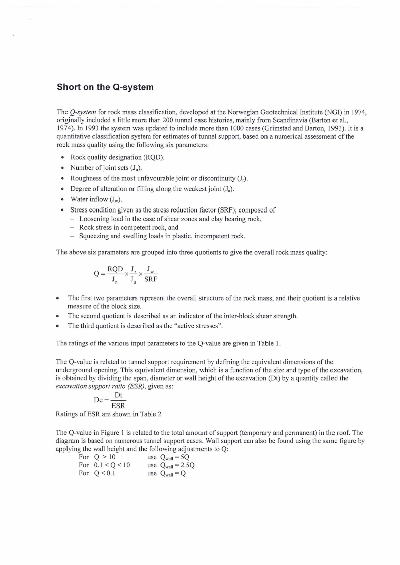
Short on the Q-system
The Q-system for rock mass classification, developed at the Norwegian Geotechnical Institute (NGI) in 1974,
originally included a little more than 200 tunnel case histories, mainly from Scandinavia (Baiton et al.,
1974). In 1993 the system was updated to include more than 1000 cases (Grimstad and Barton, 1993). It is a
quantitative classification system for estimates of tunnel support, based on a numerical assessment of the
rock mass quality using the following six parameters:
• Rock quality designation (RQD).
• Number of joint sets (111).
• Roughness of the most unfavourable joint or discontinuity (Jr)-
• Degree of alteration or filling along the weakest joint (J.).
• Water inflow (J,v).
• Stress condition given as the stress reduction factor (SRF); composed of
- Loosening load in the case of shear zones and clay bearing rock,
- Rock stress in competent rock, and
Squeezing and swelling loads in plastic, incompetent rock.
The above six parameters are grouped into three quotients to give the overall rock mass quality:
• The first two parameters represent the overall structure of the rock mass, and their quotient is a relative
measure of the block size.
• The second quotient is described as an indicator of the inter-block shear strength.
• The third quotient is described as the "active stresses".
The ratings of the various input parameters to the Q-value are given in Table I.
The Q-value is related to tunnel support requirement by defining the equivalent dimensions of the
underground opening. This equivalent dimension, which is a function of the size and type of the excavation,
is obtained by dividing the span, diameter or wall height of the excavation (Dt) by a quantity called the
excavation support ratio (ESR), given as:
De = _.!2_!_
ESR
Ratings of ESR are shown in Table 2
The Q-value in Figure I is related to the total amount of support (temporary and permanent) in the roof. The
diagram is based on numerous tunnel support cases. Wall support can also be found using the same figure by
applying the wall height and the following adjustments to Q:
For Q > 10
For 0.1 < Q < 10
use Qwall= 5Q
use Qwall= 2.5Q
For Q < 0.1
use Qwall= Q
|
|
5 Page 5 |
▲back to top |
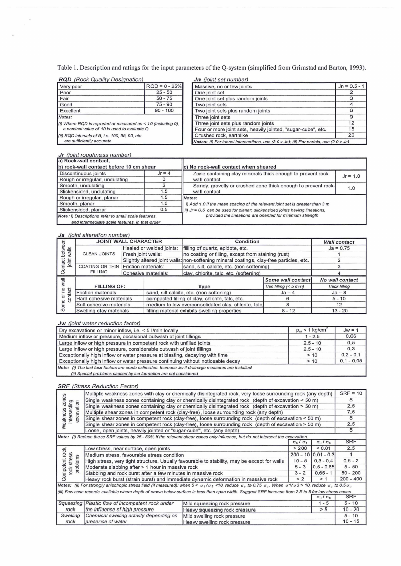
Table I. Description and ratings for the input parameters of the Q-system (simplified from Grimstad and Barton, 1993).
RQD (Rock Qualitv Desianation)
Very poor
Poor
Fair
Good
Excellent
Notes:
RQD = 0- 25%
25 -50
50- 75
75 - 90
90 - 100
(i) Where ROD is reported or measured as < 1O (including OJ,
a nominal value of 1O is used to evaluate Q
(ii) ROD intervals of 5, i.e. 100, 95, 90, etc.
are sufficiently accurate
Jn (ioint set number)
Massive, no or few joints
Jn = 0.5 - 1
One joint set
2
One joint set plus random joints
3
Two joint sets
4
Two ioint sets plus random joints
6
Three joint sets
9
Three joint sets plus random joints
12
Four or more joint sets, heavily jointed, "sugar-cube", etc.
15
Crushed rock, earthlike
20
Notes: (i) For tunnel intersections. use (3.0 x Jn): (ii) For portals. use (2.0 x Jn)
r 10,n roup hness num b er)
a) Rock-wall contact,
bl rock-wall contact before 10 cm shear
Discontinuous joints
Jr= 4
Rough or irregular, undulating
3
Smooth, undulating
2
Slickensided, undulating
1.5
Rough or irregular, planar
1.5
Smooth, planar
1.0
Slickensided, Planar
0.5
Note: i) Descriptions refer to small scale features,
and intermediate scale features. in that order
cl No rock-wall contact when sheared
Zone containing clay minerals thick enough to prevent rock-
wall contact
Sandy, gravelly or crushed zone thick enough to prevent rock
wall contact
Notes:
i) Add 1.0 if the mean spacing of the relevant joint set is greater than 3 m
ii) Jr= 0. 5 can be used for planar, s/ickensided joints having lineations,
provided the lineations are oriented for minimum strength
Jr= 1.0
1.0
J a C1'0tl,nt a era f10n num ber)
Ca,:
1 gi
2
UC·o
C: -~
u0
JOINT WALL CHARACTER
Condition
Healed or welded joints: filling of quartz, epidote, etc.
CLEAN JOINTS Fresh joint walls:
no coating or filling, except from staining (rust)
Slightly altered joint walls: non-softening mineral coatings, clay-free particles, etc.
COATING OR THIN Friction materials:
FILLING
Cohesive materials:
sand, silt, calcite, etc. (non-softening)
clav. chlorite talc etc. /softenino)
1
c 0
C:
tr5o
()
a,
E
0u
e0 n
FILLING OF:
Friction materials
Hard cohesive materials
Soft cohesive materials
Swelling clay materials
Some wa/J contact
Type
Thin filling(< 5 mm)
sand, silt calcite, etc. (non-softening)
Ja = 4
compacted filling of clay, chlorite, talc, etc.
6
medium to low overconsolidated clay, chlorite, talc,
8
filling material exhibits swelling properties
8 - 12
Wa/J contact
Ja = 0.75
1
2
3
4
No wa/J contact
Thick filling
Ja = a
5 - 10
12
13 - 20
J w C1om. t wa er re dUCf/On f.actor
Dry excavations or minor inflow, i.e. < 5 I/min locally
Medium inflow or pressure, occasional outwash of joint fillings
Large inflow or high pressure in competent rock with unfilled joints
Large inflow or high pressure, considerable outwash of joint fillings
Exceptionally high inflow or water pressure at blasting, decaying with time
Exceptionally high inflow or water pressure continuing without noticeable decay
Note: (i) The last four factors are crude estimales. Increase Jw if drainage measures are installed
(ii) Special problems caused by ice formation are not considered
Pw< 1 kg/cm'
1 - 2.5
2.5 - 10
2.5 - 10
> 10
> 10
Jw= 1
0.66
0.5
0.3
0.2 - 0.1
0.1 - 0.05
SRF (Stress Reduction Factor)
Multiple weakness zones with clay or chemically disintegrated rock, very loose surrounding rock (any depth)
Single weakness zones containing clay or chemically disintegrated rock (depth of excavation < 50 m)
Single weakness zones containing clay or chemically disintegrated rock (depth of excavation > 50 m)
Multiple shear zones in competent rock (clay-free), loose surrounding rock (any depth)
Single shear zones in competent rock (clay-free), loose surrounding rock (depth of excavation < 50 m)
Single shear zones in competent rock (clay-free), loose surrounding rock (depth of excavation > 50 m)
Loose, open ioints, heavilv iointed or "suoar-cube", etc. (anv depth)
SRF = 10
5
2.5
7.5
5
2.5
5
Note:
(i) Reduce these SRF values by 25 - 50% if the relevant shear zones only influence, but do not intersect the e~xc_a_v_a~tio_n_·~-----~---
ac I cr1 a 0 I ac
SRF
Low stress, near surface, open joints
> 200 < 0.01
2.5
Medium stress, favourable stress condition
200 - 10 0.01 - 0.3
1
High stress, very tight structure. Usually favourable to stability, may be except for walls
10 - 5 0,3 - 0.4
0.5 - 2
Moderate slabbing after > 1 hour in massive rock
5-3 0.5 - 0.65 5 - 50
Slabbing and rock burst after a few minutes in massive rock
3-2
0.65 - 1 50 - 200
Heavy rock burst (strain burst) and immediate dynamic deformation in massive rock
<2
>1
200 - 400
Notes: (ii)Forstronglyanisotropicstressfield(ifmeasured):when5<
a 1 /u, <10, reduce uc to0.75 uc. When a1/u3> 10, reduce uc to0.5uc
(iii) Few case records available where depth of crown below surface is less than span width. Suggest SRF increase from 2.5 to 5 for low stress cases
ao I ac
SRF
Squeezing
rock
Swelling
rock
Plastic flow of incompetent rock under
the influence of high pressure
Chemical swelling activity depending on
presence of water
Mild squeezing rock pressure
Heavy soueezino rock pressure
Mild swelling rock pressure
Heavy swelling rock pressure
1-5
>5
5- 10
10 - 20
5 - 10
10 - 15
|
|
6 Page 6 |
▲back to top |
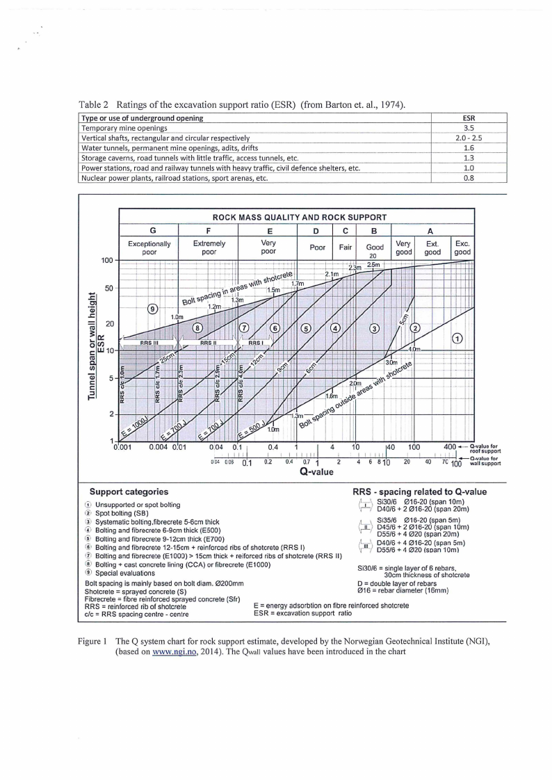
Table 2 Ratings of the excavation support ratio (ESR) (from Barton et. al., 1974).
Type or use of underground opening
Temporary mine openings
Vertical shafts, rectangular and circular respectively
Water tunnels, permanent mine openings, adits, drifts
Storage caverns, road tunnels with little traffic, access tunnels, etc.
Power stations, road and railway tunnels with heavy traffic, civil defence shelters, etc.
Nuclear power plants, railroad stations, sport arenas, etc.
ESR
3.5
2.0 - 2.5
1.6
1.3
1.0
0.8
G
Exceptionally
poor
ROCK MASS QUALITY AND ROCK SUPPORT
F
Extremely
poor
E
Very
poor
D
C
B
Poor Fair Good
20
Very
good
A
Ext.
good
Exe.
good
0.001
0.004 0.01
0.04 0.1 j
0.4 1
j4
10
140 100
400- Q-v:iuo for
~;lr~~~~"o'rt I I I I
I I I I I I II
I
I I I III
I I I , I I -, roo support
O_ll"_.00..6. -'-'--'--Q+.1-~0'-.2-'--,-;0+.-'4--'0.7~1+----'z'----'--4--'-5'-'-s""'1-+Q-~2,',0-'--4~0 -'-'-'70-'·-l1QQ
Q-value
Support categories
RRS - spacing related to Q-value
G:>Unsupported or spot bolting
@ Spot bolling (SB)
@ Systematic bolting,fibrecrete 5-6cm thick
© Bolting and fibrecrete 6-9cm thick (E500)
(i, Bolting and fibrecrete 9-12cm thick (E700)
(j) Bolting and fibrecrete 12-15cm + reinforced ribs of shotcrete (RRS I)
(i> Bolting and fibrecrete (E1000) > 15cm thick+ reiforced ribs of shotcrete (RRS II)
C1i-Bolting+ cast concrete lining (CCA) or fibrecrete (E1000)
® Special evaluations
tc:1 Si30/6 016-20 (span 10m)
11 040/6 + 2 016-20 (span 20m)
Si35/6 016-20 (span 5m)
(r11-)045/6 + 2 016-20 (span 10m)
055/6 + 4 020 (span 20m)
(11/ 11\\
040/6 + 4 016-20 (span Sm)
055/6 + 4 020 (soan 10m\\
Si30/6 = single layer of 6 rebars,
30cm thickness of sholcrete
Bolt spacing is mainly based on bolt diam. 0200mm
Sholcrele = sprayed concrete (S)
Fibrecrete = fibre reinforced sprayed concrete (Sfr)
RRS = reinforced rib of shotcrele
clc = RRS spacing centre - centre
0 = double layer of rebars
016 = rebar diameter (16mm)
E = energy adsorbtion on fibre reinforced shotcrete
ESR = excavation support ratio
Figure I The Q system chart for rock support estimate, developed by the Norwegian Geotechnical Institute (NGI),
(based on www.ngi.no, 2014). The Qwall values have been introduced in the chart
|
|
7 Page 7 |
▲back to top |
Equal Area Net
(Schmidt Net)