


 |
ECE602S- ELECTRICAL CIRCUIT AND ELECTRONICS- JAN 2020 |
|
|
1 Page 1 |
▲back to top |
NAMIBIA UNIVERSITY
OF SCIENCE AND TECHNOLOGY
FACULTY OF HEALTH AND APPLIED SCIENCES
DEPARTMENT OF NATURAL AND APPLIED SCIENCES
QUALIFICATION: BACHELOR OF SCIENCE (MAJOR AND MINOR)
QUALIFICATION CODE: 07BOSC
LEVEL: 6
COURSE NAME: ELECTRICAL CIRCUIT AND
ELECTRONICS
COURSE CODE: ECE602S
SESSION: JANUARY 2020
DURATION: 3 HOURS
PAPER: THEORY
MARKS: 100
SUPPLEMENTARY/SECOND OPPORTUNITY EXAMINATION QUESTION PAPER
EXAMINER (S)
EMMANUEL EJEMBI
MODERATOR:
SAHU DIPTI
PERMISSIBLE MATERIALS
Scientific Calculator
THIS EXAMINATION QUESTION PAPER CONSISTS OF 7 PAGES
(INCLUDING THIS FRONT PAGE)
|
|
2 Page 2 |
▲back to top |
SECTION A
QUESTION 1
[30]
Short Answer Question Types: Each question in this section carries two marks.
1.1 To obtain p-type semiconductor, the impurity added to a pure semiconductor is
(2)
a. Trivalent
b. Tetravalent
c. Pentavalent
d. None of these
1.2 A p-type and n-type semiconductor attend positive and negative charge respectively.
(2)
a. True b False
1.3 In an N-type semiconductor the majority carriers are
(2)
a. Holes b. Electrons’ c.Positiveions d. Negative ions
1.4 For Germanium PN Junction the maximum value of barrier potential is
(2)
a.0.3 volt b.O.1 volt c.1.3 volt d.1.7 volt
1.5 When a PN Junction is reverse biased.
(2)
a. The beat of the depletion layer increases
b. It offers the high resistance
c. Asmall current flows through it because of minority carriers
d. All of these
1.6 In a half wave rectifier, the load current flows
(2)
a. Only for the positive of cycle of the input signal
b. For less than half cycle of the input signal
c. For more than half cycle of the input signal
d. For whole cycle of the input signal
1.7 Zener diode is used as
(2)
a. Anamplifier b. A voltage regulator
c. Acoupler d. Arectifier
|
|
3 Page 3 |
▲back to top |
1.8 In an npn transistor with normal bias
(2)
a. Only holes cross the collector junction
b. Only the majority carriers cross the collection junction
c. The emitter junction has a high resistance
d. The emitter junction is forward biased and collector junction is reverse biased
1.9 A transistor is said to be in quiescent state when
(2)
a. It is unbiased
b. No Current flows through it
c. Emitter junction is just biased equal to collector junction.
d. No signal is applied to the input
1.10 In a pnp transistor, the current carriers are
(2)
A Acceptor ions b. Donor ions c. Free electrons d. Holes
1.11 Most of the majority carriers from the emitter
(2)
a. Recombine in the base
b. Recombine in the emitter
c. Pass through the base region to the collector
d. None of these.
1.12 When transistor are used in digital circuits, they usually operate in the
(2)
a. Active region b. Breakdown region
c. Saturated and cutoff region
d. Linear region
1.13 In a transistor, Collector current is controlled by
(2)
a. Collector voltage b. Base current. c. Collector resistor
d. All of the above
|
|
4 Page 4 |
▲back to top |
1.14 Which of the following load line equation is correct?
(2)
a. Voc = Veg = TcR,
b. Ver = Vec — IcR,
Cc. I¢R, = Voc _- Ver
d. Ver = Vec + TcR,
1.15 A differential amplifier has an open-loop voltage gain of 120. The input signals are
(2)
2.45V and 2.35V. Calculate the output voltage of the amplifier
a. 12V b. 14V c. 13V d.9V
|
|
5 Page 5 |
▲back to top |
SECTION B
QUESTION 2
[15]
2.1 Define Kirchhoff’s Current Law.
(2)
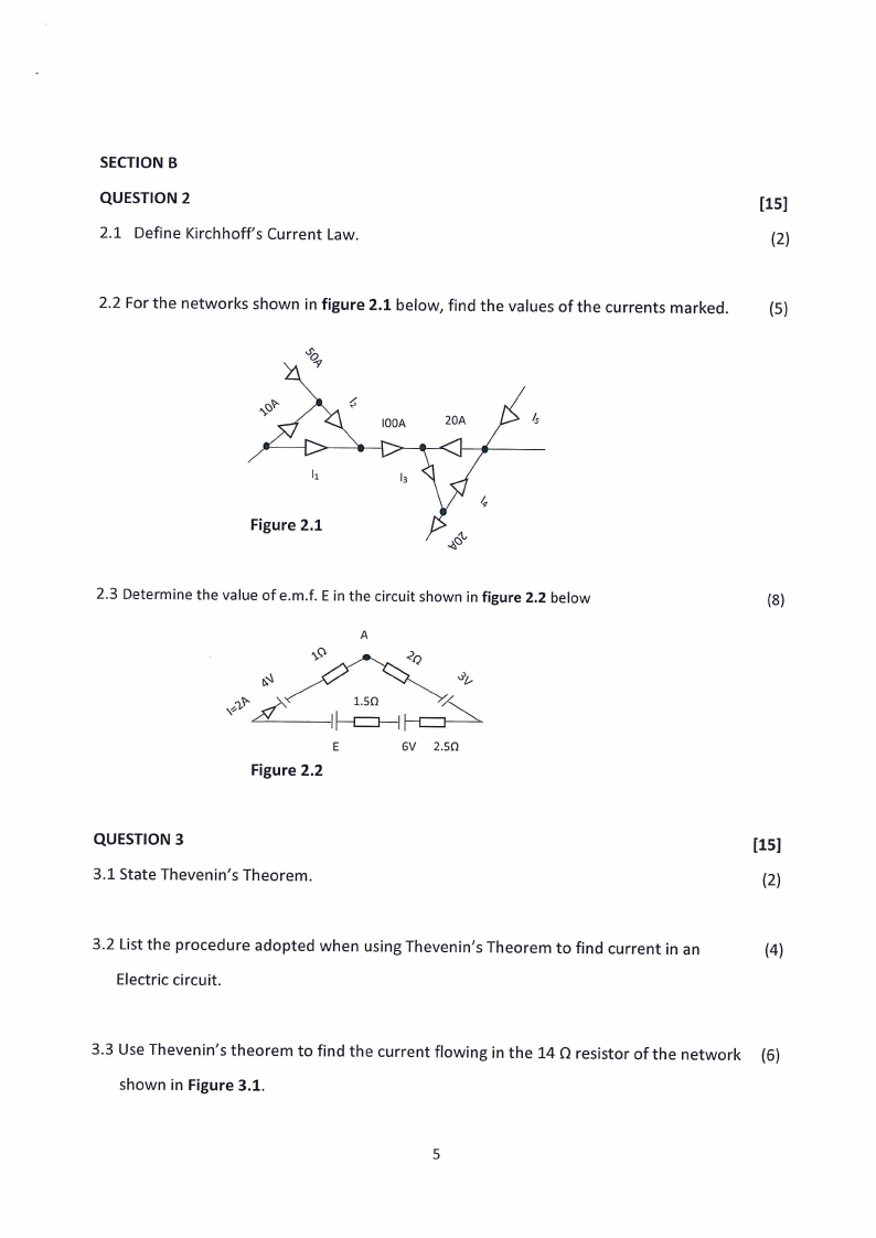
2.2 For the networks shown in figure 2.1 below, find the values of the currents marked.
(5)
Figure 2.1
&
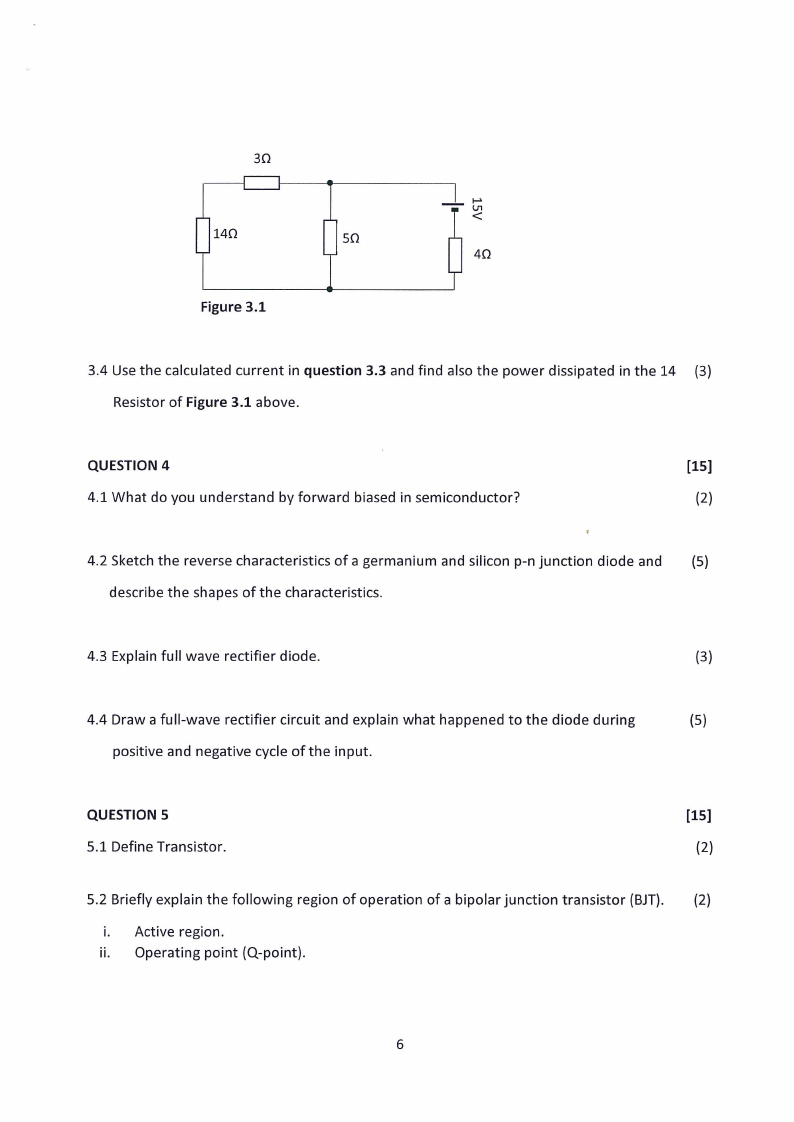
2.3 Determine the value of e.m.f. E in the circuit shown in figure 2.2 below
(8)
E
Figure 2.2
6V 2.50
QUESTION 3
[15]
3.1 State Thevenin’s Theorem.
(2)
3.2 List the procedure adopted when using Thevenin’s Theorem to find current in an
(4)
Electric circuit.
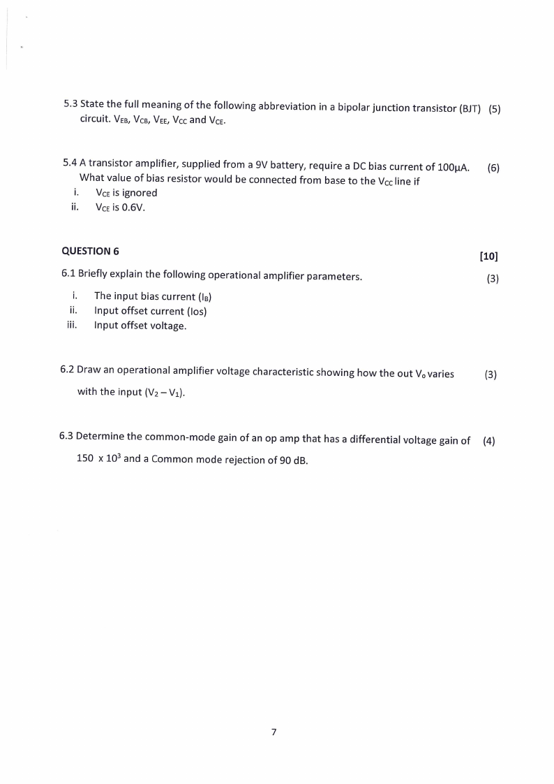
3.3 Use Thevenin’s theorem to find the current flowing in the 14 Q resistor of the network (6)
shown in Figure 3.1.
|
|
6 Page 6 |
▲back to top |
30
|
Ls
| 140
e
50
Figure 3.1
aa b
u< w
40
3.4 Use the calculated current in question 3.3 and find also the power dissipated inthe 14 (3)
Resistor of Figure 3.1 above.
QUESTION 4
[15]
4.1 What do you understand by forward biased in semiconductor?
(2)
4.2 Sketch the reverse characteristics of a germanium and silicon p-n junction diode and
(5)
describe the shapes of the characteristics.
4.3 Explain full wave rectifier diode.
(3)
4.4 Draw a full-wave rectifier circuit and explain what happened to the diode during
(5)
positive and negative cycle of the input.
QUESTION 5
[15]
5.1 Define Transistor.
(2)
5.2 Briefly explain the following region of operation of a bipolar junction transistor (BJT). (2)
i. Active region.
ii. Operating point (Q-point).
|
|
7 Page 7 |
▲back to top |
5.3 State the full meaning of the following abbreviation in a bipolar junction transistor (BJT) (5)
circuit. Ves, Vcp, Vee, Vcc and Vce.
5.4 A transistor amplifier, supplied from a 9V battery, require a DC bias current of 100pA.
~=(6)
What value of bias resistor would be connected from base to the Vecline if
i. Vceis ignored
ii, Vce is 0.6V.
QUESTION 6
[10]
6.1 Briefly explain the following operational amplifier parameters.
(3)
i. The input bias current (Is)
ii. Input offset current (los)
iii. Input offset voltage.
6.2 Draw an operational amplifier voltage characteristic showing how the out Vo varies
(3)
with the input (V2 —V3).
6.3 Determine the common-mode gain of an op amp that has a differential voltage gain of (4)
150 x 10? and a Common mode rejection of 90 dB.